Damage-tolerant design
Damage-Tolerant Design in Mechanical Engineering:
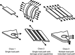
Damage-tolerant design is an engineering approach in which a component is designed
to remain safe and functional even when cracks, defects, corrosion, or other
forms of damage are present.
Fundamental principles:
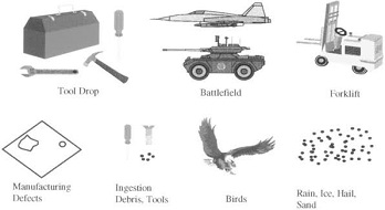
1. Initial flaw assessment: Identify possible manufacturing defects, existing cracks,
corrosion, and material imperfections.
2. Crack growth prediction: Calculate how cracks may grow under repeated loading,
vibration, pressure, and temperature changes.
3. Inspection and monitoring:
Use nondestructive testing (NDT) to detect cracks without damaging the component.
4. Safe repair or replacement: Establish inspection intervals and repair limits
so damage is addressed before the component becomes unsafe.
2. Damage-tolerant design workflow: Define loads and service conditions,
Stress, vibration, temperature and load cycles.
Assume an initial detectable flaw: Based on manufacturing quality and inspection capability
Calculate crack growth and critical crack size: Fracture mechanics and fatigue analysis
Establish inspection and maintenance intervals: Include uncertainty and safety margins.
Verify safety throughout service life: Inspect, repair, replace or retire as required.
3. Practical applications:
Aerospace engineering: Aircraft fuselage panels, wing structures, landing gear and turbine
components must tolerate specified damage until inspection or maintenance.
Pressure vessels and pipelines: Crack assessment considers pressure cycles,
weld defects, corrosion and material toughness.
Railway and automotive systems: Axles, wheels, suspension components and chassis structures
are assessed for fatigue cracking and safe service life.
Industrial machinery: Shafts, gears, rotors and other cyclically loaded components are designed
and maintained to reduce the risk of sudden failure.
4. Damage-tolerant design vs. safe-life design: Feature Damage-tolerant design Safe-life design.
Main assumption Flaws may exist and grow: Component has a defined finite service life.
Main method: Crack growth and fracture assessment: Fatigue life estimation and life limits.
Inspection: Central to the strategy: Depends on the application and certification basis.
5. Worked conceptual example: Consider a steel component with a small surface crack
subjected to repeated tensile loading.
The engineer would:
1. Determine the applied stress range and geometry factor.
2. Calculate the stress intensity factor at different crack sizes.
3. Use fatigue crack growth data to estimate the number of cycles required for the crack to grow.
4. Calculate the critical crack size using fracture toughness and the design conditions.
5. Set inspection intervals that provide adequate time to detect and repair the crack
before the permitted limit is reached.
The exact remaining life cannot be determined from crack sizes alone; stress history,
material properties, geometry, environment and inspection capability are also required.
Wishing you all the best,
http://www.seeyourneeds.in