Printed Circuit Boards:
Printed Circuit Boards (PCBs) form the Backbone of all major Electronics.
PCB routes Electrical signals through Electronics, which satisfies the
device Electrical and Mechanical Circuit requirements. PCBs Tell the
Electricity where to go, Bringing your Electronics to life.
Circuit Designers:
Before PCB Design, Circuit Designers are recommended to get a tour of a PC board
Shop and Communicate with Fabricators face to face over their PCB Manufacturing
Demands. Hopefully it gives Circuit Designers and those new to PCB Industry
a clear view on how Printed Circuit Boards are Manufactured, and Avoid Making
those Unnecessary errors.
PCB Manufacturing Process Steps:
Design and Output:
Circuit Boards should be Rigorously compatible with, the Designer creates a PCB Layout
using PCB Design software. Commonly-used PCB Design software includes Altium Designer,
OrCAD, Pads, KiCad, Eagle etc. Once the PCB Design is approved for Production, Designers
export the Design into Format their Manufacturers support.
PCB Design Software:
Different PCB Design Software Possibly calls for different Gerber file generation Steps,
they all encode Comprehensive vital information including Copper Tracking Layers, Drill
Drawing, Apertures, Component Notations and other Options. The software Performs
oversight algorithms on the Design to ensure that no errors go undetected.
From File to Film:
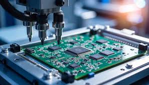
PCB printing begins after Designers output the PCB schematic files and Manufacturers
conduct a DFM check. Manufacturers use a special printer called a Plotter, which makes
photo Films of the PCBs, to print Circuit Boards. Manufacturers will use the Films to
image the PCBs. Although it is a Laser Printer, it is not a standard Laser jet Printer.
The outer Layers follow the Opposite Pattern:
Clear for Copper, but black refers to the area that will be etched away. The Plotter
automatically develops the Film, and the Film is securely stored to prevent any
unwanted contact.
Registration Holes should be Punched:
To achieve perfect alignment of all Films, Registration Holes should be Punched
through all Films. When the Tiny Calibrations of the Table Lead to an Optimal Match,
the Hole is Punched. The Holes will fit into the registration Pins in the next step
of the imaging process.
Laminate Board:
The basic form of PCB comprises a laminate board whose core material is epoxy
resin and glass fiber that are also called substrate material. Substrate
Material provides a Sturdy and Dust Resistant starting Point for the PCB.
Copper is Pre Bonded on both sides. The process involves whittling away
the Copper to Reveal the Design from the Films.
What does a Printed Circuit Board do:
A Printed Circuit Board, or PCB, is used to Mechanically support and Electrically
connect Electronic components using Conductive Pathways, Tracks or Signal traces
Etched from Copper Sheets Laminated onto a Non-conductive substrate.
What is a Printed Circuit Board called:
The PCB revolutionized electrical engineering. The PCB made it possible to
mass produce Electronic devices for the first time. Printed Circuit Board
is the most common name but may also be called "Printed wiring Boards" or
"Printed wiring cards".
What is the difference between PCB and PWB:
When comparing PWB vs PCB, one difference that comes out is that PCB refers
to a Board with a complete Circuit while PWB focuses on the Board rather
than the course.
What is a Printed Circuit Board made of:
Printed Circuit Boards (PCBs) are usually a Flat Laminated Composite made from
Non-conductive substrate materials with Layers of Copper Circuitry buried
internally or on the external surfaces. They can be as simple as one or
two Layers of Copper, or in high density applications they can have fifty
Layers or more.
How much is a Printed Circuit Board:
Printed Circuit Boards have a huge range of Quality, Reliability, Complexity,
and Price points. A Circuit Board typically costs from 50 cents to $300 dollars
to produce, depending on your needs.
How do you print a Circuit Board: For this tutorial,
let us consider making a PCB for a simple project, a Touch Switch using IC555.
STEP 1: Take a printout of Circuit Board layout.
STEP 2: Cut the Copper Plate for the Circuit Board.
STEP 3: Transfer the PCB Print onto the Copper Plate.
STEP 4: Iron the Circuit from the Paper onto the PCB Plate.
Why are PCB green:
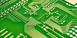
It is due to the Solder Mask, which protects the Copper Circuits Printed
on the Fibre Glass core to prevent short Circuits, Soldering errors, etc.
The Colour of the Solder Mask gives the Board its appearance.
Which Circuit Board is used in all Electronic systems:
Microprocessor is the main Hardware that Drives the computer. It is a large
Printed Circuit Board (PCB), which is used in all Electronic Systems such
as Computer, Calculator, Digital system, etc.
How many types of PCB are there:
Three ways are used for the construction of PCB called single sided,
Double sided and MultiLayered. Required components are connected Electrically
with the PCB Board using two different Method named as through Hole technology
and Surface mount Technology.
Why Copper is used in PCB:
Copper is an excellent Electric and Thermal Conductor, thus improving heat
transfer along and across the PCB, which reduces the damaging stress caused
by uneven heating of the PCB. The stress otherwise may result in
micro-fracturing of the PCB, and thus device failure.
What are the components on a Circuit Board:
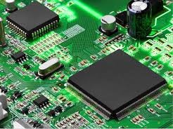
The following common components are used in most Printed Circuit Boards:
Resistors. Resistors control the electric currents that pass through them,
as well as the voltage in each component connected to them.
Transistors, Capacitors, Inductors, Diodes.
Why is Gold used on Circuit Boards:
Gold conducts electricity very efficiently, an obvious requirement for PCB
applications, It can carry small amounts of Current, essential for today
Electronic devices. Other metals can be alloyed with Gold such as nickel
or Cobalt. It does not Tarnish or Corrode, making it a reliable connection
medium.
What are the 4 basic Components of a Circuit:
Every Electric Circuit, regardless of where it is or how large or small it is,
has four basic parts: an energy source (AC or DC), a conductor (wire), an
Electrical load (device), and at least one Controller (switch). Visualize
what happens when you switch on a room light.
What are the 5 components of Electricity:
Below you will find information about the most common electrical components:
Resistors. The very first component that you should know about is the resistor.
Capacitors, Light Emitting Diode (LED), Transistors, Inductors, Integrated Circuit.
Wishing you all the best,
http://www.seeyourneeds.in