Introduction:
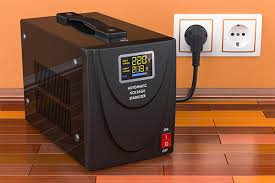
The Circuit of an Automatic Voltage Stabilizer (AVS) described in this
fact very simple in Design and will give a good Protection to the Electronic
Gadget that is Connected to it. It will Particularly Guard them against the
Dangerous high Voltages and also from the Possible Brownouts (low Voltages).
The output will stay in the range of 200VAC – 255VAC with an input Voltage
of 175VAC – 280VAC.
How does a Voltage Stabilizer Work:
The Circuit of a Voltage Stabilizer Consists of a Voltage Sensor. It is
Configured to Detect the Rise or Fall of the AC Mains Voltage to Dangerous
Levels. As soon it Senses a Risky input Voltage, it immediately Energizes the
Relays connected to it. These Relays in Turn Swaps and Switches the appropriate
Winding Terminals of the auto Transformer to Correct and Stabilize the output
Voltage.
Circuit Description:
Automatic Voltage Stabilizer Circuit Diagram. Referring to the figure,
we see that Transistor T1 Forms the main active part of the Entire Circuit.
How do you use automatic Voltage Stabilizer:
It is an Electrical appliance that Feeds Constant Voltage to a Load during over
and under Voltage Conditions. This Device Detects these Voltage conditions and
Correspondingly brings the Voltage to desired range. Voltage Stabilizers provide
a means to Regulate the supply Voltage to the Load.
How do you test a Voltage Stabilizer:
Hook the Negative side of the Battery to the Stabilizer case, as you indicated,
the Positive side of the Battery to the input Terminal of the Stabilizer. Now
with the Multimeter set to the appropriate DC volt Range, place one of the
Meter Probes on the Stabilizer Case, and the other to the Output Terminal.
Why do we use Voltage Stabilizer:
A Voltage Stabilizer is an electrical appliance used to feed constant Voltage
current to electrical gadgets like ACs and computers, and protects them from
damage due to Voltage fluctuations.
Wishing you all the best,
http://www.seeyourneeds.in